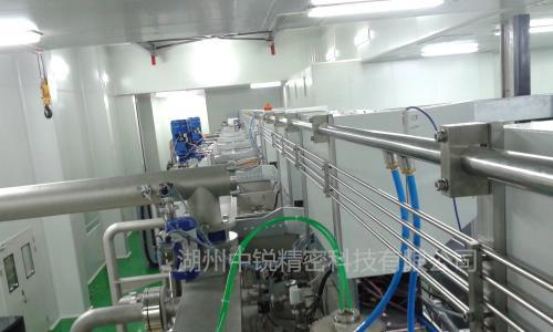
The 909 Project Very Large Scale Integrated Circuit Factory is a major construction project of my country’s electronics industry during the Ninth Five-Year Plan to produce chips with a line width of 0.18 microns and a diameter of 200 mm.

The manufacturing technology of very large-scale integrated circuits not only involves high-precision technologies such as micro-machining, but also places high requirements on gas purity.
The bulk gas supply for Project 909 is provided by a joint venture between Praxair Utility Gas Co., Ltd. of the United States and relevant parties in Shanghai to jointly establish a gas production plant.The gas production plant is adjacent to the 909 project factory building, covering an area of approximately 15,000 square meters. The purity and output requirements of various gases
High-purity nitrogen (PN2), nitrogen (N2), and high-purity oxygen (PO2) are produced by air separation. High-purity hydrogen (PH2) is produced by electrolysis. Argon (Ar) and helium (He) are purchased outsourced. The quasi-gas is purified and filtered for use in Project 909. Special gas is supplied in bottles, and the gas bottle cabinet is located in the auxiliary workshop of the integrated circuit production plant.
Other gases also include clean dry compressed air CDA system, with a usage volume of 4185m3/h, a pressure dew point of -70°C, and a particle size of no more than 0.01um in the gas at the point of use. Breathing compressed air (BA) system, usage volume 90m3/h, pressure dew point 2℃, particle size in the gas at the point of use is not greater than 0.3um, process vacuum (PV) system, usage volume 582m3/h, vacuum degree at the point of use -79993Pa . Cleaning vacuum (HV) system, usage volume 1440m3/h, vacuum degree at use point -59995 Pa. The air compressor room and vacuum pump room are both located in the 909 project factory area.
Selection of pipe materials and accessories
The gas used in VLSI production has extremely high cleanliness requirements. High-purity gas pipelines are usually used in clean production environments, and their cleanliness control should be consistent with or higher than the cleanliness level of the space in use! In addition, high-purity gas pipelines are often used in clean production environments. Pure hydrogen (PH2), high-purity oxygen (PO2) and some special gases are flammable, explosive, combustion-supporting or toxic gases. If the gas pipeline system is improperly designed or the materials are improperly selected, not only will the purity of the gas used at the gas point decrease, but it will also fail. It meets the process requirements, but it is unsafe to use and will cause pollution to the clean factory, affecting the safety and cleanliness of the clean factory.
The guarantee of the quality of high-purity gas at the point of use not only depends on the accuracy of gas production, purification equipment and filters, but is also affected to a large extent by many factors in the pipeline system. If we rely on gas production equipment, purification equipment and filters It is simply incorrect to impose infinitely higher precision requirements to compensate for improper gas piping system design or material selection.
During the design process of the 909 project, we followed the “Code for Design of Clean Plants” GBJ73-84 (the current standard is (GB50073-2001)), “Code for Design of Compressed Air Stations” GBJ29-90, “Code for Design of Oxygen Stations” GB50030-91 , “Code for Design of Hydrogen and Oxygen Stations” GB50177-93, and relevant technical measures for the selection of pipeline materials and accessories. “Code for Design of Clean Plants” stipulates the selection of pipeline materials and valves as follows:
(1) If the gas purity is greater than or equal to 99.999% and the dew point is lower than -76°C, 00Cr17Ni12Mo2Ti low-carbon stainless steel pipe (316L) with electropolished inner wall or OCr18Ni9 stainless steel pipe (304) with electropolished inner wall should be used. The valve should be a diaphragm valve or bellows valve.
(2) If the gas purity is greater than or equal to 99.99% and the dew point is lower than -60°C, OCr18Ni9 stainless steel tube (304) with electropolished inner wall should be used. Except for bellows valves that should be used for combustible gas pipelines, ball valves should be used for other gas pipelines.
(3) If the dew point of dry compressed air is lower than -70°C, OCr18Ni9 stainless steel pipe (304) with polished inner wall should be used. If the dew point is lower than -40℃, OCr18Ni9 stainless steel pipe (304) or hot-dip galvanized seamless steel pipe should be used. The valve should be a bellows valve or a ball valve.
(4) The valve material should be compatible with the connecting pipe material.

According to the requirements of specifications and relevant technical measures, we mainly consider the following aspects when selecting pipeline materials:
(1) The air permeability of pipe materials should be small. Pipes of different materials have different air permeability. If pipes with greater air permeability are selected, pollution cannot be removed. Stainless steel pipes and copper pipes are better at preventing the penetration and corrosion of oxygen in the atmosphere. However, since stainless steel pipes are less active than copper pipes, copper pipes are more active in allowing moisture in the atmosphere to penetrate into their inner surfaces. Therefore, when selecting pipes for high-purity gas pipelines, stainless steel pipes should be the first choice.
(2) The inner surface of the pipe material is adsorbed and has a small effect on analyzing the gas. After the stainless steel pipe is processed, a certain amount of gas will be retained in its metal lattice. When high-purity gas passes through, this part of the gas will enter the air flow and cause pollution. At the same time, due to adsorption and analysis, the metal on the inner surface of the pipe will also produce a certain amount of powder, causing pollution to the high-purity gas. For piping systems with purity above 99.999% or ppb level, 00Cr17Ni12Mo2Ti low carbon stainless steel pipe (316L) should be used.
(3) The wear resistance of stainless steel pipes is better than that of copper pipes, and the metal dust generated by air flow erosion is relatively less. Production workshops with higher requirements for cleanliness can use 00Cr17Ni12Mo2Ti low carbon stainless steel pipes (316L) or OCr18Ni9 stainless steel pipes ( 304), copper pipes shall not be used.
(4) For piping systems with gas purity above 99.999% or ppb or ppt levels, or in clean rooms with air cleanliness levels of N1-N6 specified in the “Clean Factory Design Code”, ultra-clean pipes or EP ultra-clean pipes should be used. Clean “clean tube with ultra-smooth inner surface”.
(5) Some of the special gas pipeline systems used in the production process are highly corrosive gases. The pipes in these pipeline systems must use corrosion-resistant stainless steel pipes as pipes. Otherwise, the pipes will be damaged due to corrosion. If corrosion spots occur on the surface, ordinary seamless steel pipes or galvanized welded steel pipes shall not be used.
(6) In principle, all gas pipeline connections should be welded. Since welding of galvanized steel pipes will destroy the galvanized layer, galvanized steel pipes are not used for pipes in clean rooms.
Taking the above factors into consideration, the gas pipeline pipes and valves selected in the &7& project are as follows:
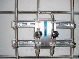
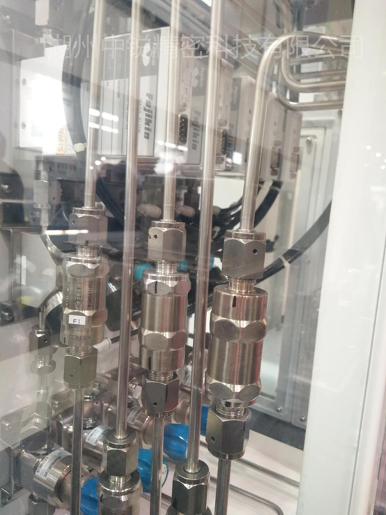
The high-purity nitrogen (PN2) system pipes are made of 00Cr17Ni12Mo2Ti low-carbon stainless steel pipes (316L) with electropolished inner walls, and the valves are made of stainless steel bellows valves of the same material.
The nitrogen (N2) system pipes are made of 00Cr17Ni12Mo2Ti low-carbon stainless steel pipes (316L) with electropolished inner walls, and the valves are made of stainless steel bellows valves of the same material.
The high-purity hydrogen (PH2) system pipes are made of 00Cr17Ni12Mo2Ti low-carbon stainless steel pipes (316L) with electropolished inner walls, and the valves are made of stainless steel bellows valves of the same material.
The high-purity oxygen (PO2) system pipes are made of 00Cr17Ni12Mo2Ti low-carbon stainless steel pipes (316L) with electro-polished inner walls, and the valves are made of stainless steel bellows valves of the same material.
Argon (Ar) system pipes are made of 00Cr17Ni12Mo2Ti low-carbon stainless steel pipes (316L) with electropolished inner walls, and stainless steel bellows valves of the same material are used.
The helium (He) system pipes are made of 00Cr17Ni12Mo2Ti low-carbon stainless steel pipes (316L) with electropolished inner walls, and the valves are made of stainless steel bellows valves of the same material.
The clean dry compressed air (CDA) system pipes are made of OCr18Ni9 stainless steel pipes (304) with polished inner walls, and the valves are made of stainless steel bellows valves of the same material.
The breathing compressed air (BA) system pipes are made of OCr18Ni9 stainless steel pipes (304) with polished inner walls, and the valves are made of stainless steel ball valves of the same material.
The process vacuum (PV) system pipes are made of UPVC pipes, and the valves are made of vacuum butterfly valves made of the same material.
The cleaning vacuum (HV) system pipes are made of UPVC pipes, and the valves are made of vacuum butterfly valves made of the same material.
The pipes of the special gas system are all made of 00Cr17Ni12Mo2Ti low-carbon stainless steel pipes (316L) with electropolished inner walls, and the valves are made of stainless steel bellows valves of the same material.
3 Construction and installation of pipelines
3.1 Section 8.3 of the “Clean Factory Building Design Code” stipulates the following provisions for pipeline connections:
(1) Pipe connections should be welded, but hot-dip galvanized steel pipes should be threaded.The sealing material of threaded connections shall comply with the requirements of Article 8.3.3 of this specification
(2) Stainless steel pipes should be connected by argon arc welding and butt welding or socket welding, but high-purity gas pipelines should be connected by butt welding without marks on the inner wall.
(3) The connection between pipelines and equipment should comply with the connection requirements of the equipment.When using hose connections, metal hoses should be used
(4) The connection between pipelines and valves should comply with the following regulations
① The sealing material connecting high-purity gas pipelines and valves should use metal gaskets or double ferrules according to the requirements of the production process and gas characteristics.
②The sealing material at the threaded or flange connection should be polytetrafluoroethylene.
3.2 According to the requirements of specifications and relevant technical measures, the connection of high-purity gas pipelines should be welded as much as possible. Direct butt welding should be avoided during welding. Pipe sleeves or finished joints should be used. The pipe sleeves should be made of the same material and inner surface smoothness as the pipes. level, during welding, in order to prevent oxidation of the welding part, pure protective gas should be introduced into the welding pipe. For stainless steel pipes, argon arc welding should be used, and argon gas of the same purity should be introduced into the pipe. Threaded connection or threaded connection must be used. When connecting flanges, ferrules should be used for threaded connections. Except for oxygen pipes and hydrogen pipes, which should use metal gaskets, other pipes should use polytetrafluoroethylene gaskets. Applying a small amount of silicone rubber to the gaskets will also be effective. Enhance sealing effect. Similar measures should be taken when flange connections are made.
Before installation work begins, a detailed visual inspection of pipes, fittings, valves, etc. must be carried out. The inner wall of ordinary stainless steel pipes should be pickled before installation. The pipes, fittings, valves, etc. of oxygen pipelines should be strictly prohibited from oil, and should be strictly degreased according to relevant requirements before installation.
Before the system is installed and put into use, the transmission and distribution pipeline system should be completely purged with the delivered high-purity gas. This not only blows away the dust particles that accidentally fell into the system during the installation process, but also plays a drying role in the pipeline system, removing part of the moisture-containing gas absorbed by the pipe wall and even the pipe material.
4. Pipeline pressure test and acceptance
(1) After the system is installed, 100% radiographic inspection of the pipes transporting highly toxic fluids in special gas pipelines shall be carried out, and their quality shall not be lower than Level II. Other pipes shall be subject to sampling radiographic inspection, and the sampling inspection ratio shall not be less than 5 %, the quality shall not be lower than grade III.
(2) After passing the non-destructive inspection, a pressure test should be carried out. In order to ensure the dryness and cleanliness of the piping system, a hydraulic pressure test must not be carried out, but a pneumatic pressure test should be used. The air pressure test should be carried out using nitrogen or compressed air that matches the cleanliness level of the clean room. The test pressure of the pipeline should be 1.15 times the design pressure, and the test pressure of the vacuum pipeline should be 0.2MPa. During the test, the pressure should be gradually and slowly increased. When the pressure rises to 50% of the test pressure, if no abnormality or leakage is found, continue to increase the pressure step by step by 10% of the test pressure, and stabilize the pressure for 3 minutes at each level until the test pressure. Stabilize the pressure for 10 minutes, then reduce the pressure to the design pressure. The pressure stop time should be determined according to the needs of leak detection. The foaming agent is qualified if there is no leakage.
(3) After the vacuum system passes the pressure test, it should also conduct a 24-hour vacuum degree test according to the design documents, and the pressurization rate should not be greater than 5%.
(4) Leakage test. For ppb and ppt grade pipeline systems, according to relevant specifications, no leakage should be considered as qualified, but the leakage amount test is used during design, that is, the leakage amount test is performed after the air tightness test. The pressure is the working pressure, and the pressure is stopped for 24 hours. The average hourly leakage is less than or equal to 50ppm as qualified. The calculation of the leakage is as follows:
A=(1-P2T1/P1T2)*100/T
In the formula:
A-hour leakage (%)
P1-Absolute pressure at the beginning of the test (Pa)
P2-Absolute pressure at the end of the test (Pa)
T1-absolute temperature at the beginning of the test (K)
T2-absolute temperature at the end of the test (K)
Post time: Dec-12-2023


